


Illuminated pushbutton switch TP/TPL

-
●To buy this product, please go to the following Online Web stores.

Ultra-Miniature Pushbutton Switches
-
Long Travel DPDT ultra-miniature switch with long travel (latch position: 1 mm, total travel: 1.5 mm).
-
High Contact Reliability Clip type contact mechanism ensures high reliability
-
PC Board Mount Terminal pitch is in inches (multiples of 2.54 mm) for all models. The unique terminal shape prevents the terminal pins from coming loose from the PC board during dip soldering
-
Epoxy Sealed Terminals Epoxy sealed terminals prevent ingress of flux
-
Wide Variety of Accessories Wide selection of accessories including color buttons, mounting frames, and LED illuminations are available
-
Unified Mounting Height The mounting height of the TP/TPL series is the same as the LTR/LTM series which makes it convenient to design into the same panel.
Specifications
| Rating | Silver plated contacts: 0.1 A 30 VDC max. Gold plated contacts: 30 VDC 0.1 A Max. 1 μA min. |
|---|---|
| Initial contact resistance | Silver plated contacts: 50 mΩ max. (1.5 mA 200 μVAC) Gold plated contacts: 100 mΩ max. (1.5 mA 200 μVAC) |
| Dielectric strength | 500 VAC 1 minute |
| Insulation resistance | 100 MΩ min. (500 VDC) |
| Electrical life | 10,000 operations |
| Operating force | TP: 1.47 ±0.98 N (Momentaly) TPL: 2.45 ±0.98 N (Push to lock) |
| Operating temperature range | ⁻10 ~ +70 ℃ |
| Storage temperature range | ー25 ~ +85 ℃ |
Part number designation
| T | P | L | 1- | 01 | G- | L2 | |
|---|---|---|---|---|---|---|---|
|
Series code |
Timing of switching P:Non-shorting |
Operation type none:Momentary L:Push to lock |
Structure |
Registration No. |
Contact plating None:Silver G:Gold |
LED color None:Without LED L2:Red L5:Green L8:Yellow |
|
List of part numbers
| Part No. | Contact plating | LED color | Operation type | CAD |
|---|---|---|---|---|
| TP1-01 | Silver | ― | Momentary | |
| TPL1-01 | Silver | ― | Push to lock | |
| TP2-01 | Silver | ― | Momentary | |
| TPL2-01 | Silver | ― | Push to lock | |
| ★TP1-01G | Gold plated | ― | Momentary | |
| ★TP2-01G | Gold plated | ― | Momentary | |
| ★TPL2-01G | Gold plated | ― | Push to lock | |
| ☆TP2-01-L2 | Silver | Red | Momentary | |
| TP2-01-L5 | Silver | Green | Momentary | |
| ☆TP2-01-L8 | Silver | Yellow | Momentary | |
| ★TP2-01G-L2 | Gold plated | Red | Momentary | |
| ★TP2-01G-L5 | Gold plated | Green | Momentary | |
| ★TP2-01G-L8 | Gold plated | Yellow | Momentary | |
| ☆TPL2-01-L2 | Silver | Red | Push to lock | |
| TPL2-01-L5 | Silver | Green | Push to lock | |
| ☆TPL2-01-L8 | Silver | Yellow | Push to lock | |
| ★TPL2-01G-L2 | Gold plated | Red | Push to lock | |
| ★TPL2-01G-L5 | Gold plated | Green | Push to lock | |
| ★TPL2-01G-L8 | Gold plated | Yellow | Push to lock |
★: Made to order products
Optional Accessories
1. Color buttons
| Size | Illuminated type or Non | Color | Part No. | Outline dimensions |
|---|---|---|---|---|
| □7.5 ㎜ | Without LED | Black | 140007480234 | 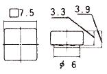 |
| Gray | 140007480235 | |||
| White | 140007480236 | |||
| Ivory | 140007480237 | |||
| Red | 140007480231 | |||
| With LED | Clear | 140007480466 | ||
| Red clear | 140007480238 | |||
| Green clear | 140007480239 | |||
| Yellow clear | 140007480240 | |||
| Φ7.5 ㎜ | Without LED | Black | 140007480272 | 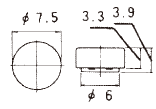 |
| Gray | 140007480273 | |||
| White | 140007480274 | |||
| Red | 140007480269 | |||
| With LED | Clear | 140007480467 | ||
| Red clear | 140007480276 | |||
| Green clear | 140007480277 | |||
| Yellow clear | 140007480278 | |||
| □10 ㎜ | Without LED | Black | 140007480244 | 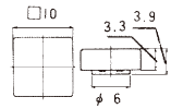 |
| Gray | 140007480245 | |||
| White | 140007480246 | |||
| Ivory | 140007480247 | |||
| Red | 140007480241 | |||
| Φ10 ㎜ | Without LED | Black | 140007480282 | 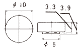 |
| Gray | 140007480283 | |||
| White | 140007480284 | |||
| Ivory | 140007480285 | |||
| Red | 140007480279 |
2. Mounting frames
| Applicable size | Color | Part No. | Outline dimensions |
|---|---|---|---|
| for □7.5 ㎜ | Black | 140000340191 | 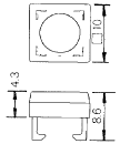 |
| Gray | 140000340192 | ||
| White | 140000340193 | ||
| Ivory | 140000340194 | ||
| for Φ7.5 ㎜ | Black | 140000340195 | 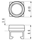 |
| Gray | 140000340196 | ||
| White | 140000340197 | ||
| for □10 ㎜用 | Black | 140000340187 | 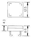 |
| Gray | 140000340188 | ||
| White | 140000340189 | ||
| for Φ10 ㎜用 | Black | 140000340199 | 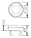 |
| Gray | 140000340200 | ||
| White | 140000340201 | ||
| Ivory | 140000340202 |
Handling Precautions
◆Soldering Specifications
- Manual Soldering
Device: Soldering iron
①380°C, Max.; 3 second, Max. - Wave Soldering/ Device: Jet wave type or dip type
①245°C; 3 seconds, Max. - Pre-heating should be done at temperatures below 80°C to 120°C and within 120 seconds.
- For TPL type, soldering should be done with the lock released.
- Do not dip solder the switches with color buttons or mounting frames attached. Soldering heat may deform the accessorie or cause ingress of flux.
◆Flux Cleaning
- Solvents : Fluorine or Alcohl type
- The TP/TPL series are not washable. To wash the PC board,clean the soldering surface of the PC board with a brush so that the switch is not exposed to the cleaning solution.
- After soldering, wait until the temperature of the terminals cool down to 90℃ or below or until the parts are exposed to room temperature for more than 5 min. before washing.
◆Switch Operation
- Operating force should be 9.8 N or less.
- Do not operate the switch right after soldering.
- Do not solder the switch with the actuator pressed down.
Documents
Environmental Data
- ●The above contents and descriptions are subject to change without notice.
